


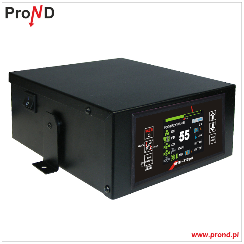
Sterownik IRYD RTZ PID 601 RS
- Dodaj recenzję:
- Symbol produktu: 601
- Producent: ProND
Menu: IRYD RTZ PID RS KOLOR
Wersje językowe
Cechy szczególne
Funkcje sterownika
Wersje wykonania
Układy pracy regulatora
Instrukcje
OPIS PODSTAWOWY
IRYD RTZ Pid Fuzzy Logic KOLOR jest regulatorem przeznaczonym do kontroli pracy kotła CO z podajnikiem ślimakowym lub tłokowym (z czujnikiem położenia podajnika). Regulator steruje rozbudowaną instalacją grzewczą. Specjalnie zaprojektowane menu umożliwia stopniowe uaktywnianie kolejnych funkcji oraz możliwości regulatora.
Regulator ten posiada specjalny algorytm pracy pid fuzzy logic, który po określeniu przez użytkownika maksymalnej i minimalnej mocy kotła potrafi w sposób płynny dobierać odpowiednie dawki opału w zależności od obciążenia instalacji oraz rodzaju opału. Regulator steruje w sposób ciągły pracą dmuchawy dobierając do danej prędkości dmuchawy odpowiednią ilość opału. Ponadto wersja ta wyposażona jest w dodatkowy algorytm pid wpływający na temperaturę spalin regulujący moc kotła tak aby wartość temperatury spalin nie przekraczała maksymalnej zadanej przez użytkownika. Te nowoczesne algorytmy sterowania pozwalają zaoszczędzić na ilości spalanego opału, a co za tym idzie ma to korzystny wpływ na środowisko naturalne. W Iryd RTZ PID RS zastosowano komunikację RS 232 ProND co pozwoliło rozszerzyć możliwości jego działania. RS232 ProND pozwala między innymi na podłączenie sterownika do modułu LAN. Komunikacja ta w porównaniu z 1 - Wire pozwoliła zwiększyć zakres funkcji służących do zdalnego sterowania pracą regulatora.
WERSJE JĘZYKOWE


FUNKCJE
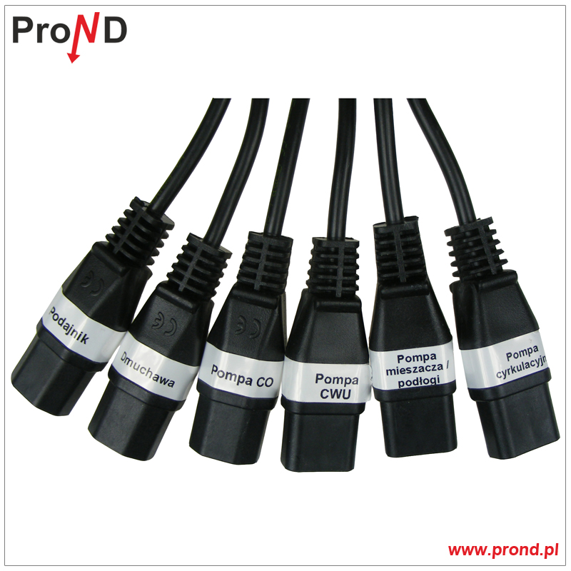
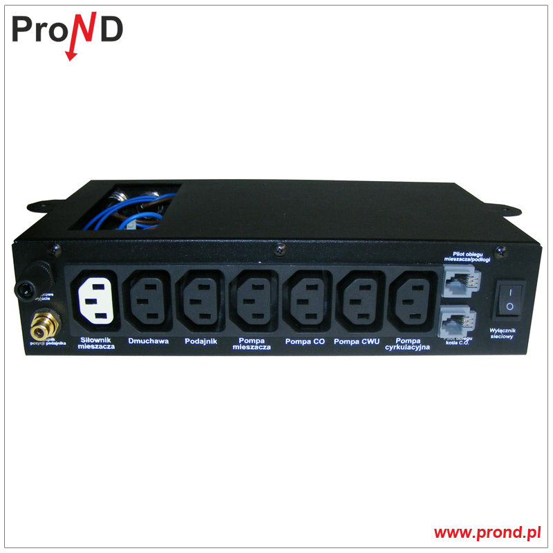
- płynne sterowanie obrotami dmuchawy
- sterowanie podajnikiem z możliwością wycofania przy zacięciu (dostępne tylko w przypadku podajnika tłokowego)
- sterowanie pompą obiegową CO
- sterowanie pompą ładującą zasobnik CWU
- sterowanie drugim obiegiem grzewczym - pompą mieszacza lub pompą instalacji podłogowej
- sterowanie siłownikiem zaworu mieszającego
- sterowanie pompą cyrkulacyjną, która może być używana w obiegu cyrkulacji CWU lub cyrkulacji CO
- obsługa dwóch PILOTÓW lub termostatów pokojowych (dwa niezależne obiegi)
- możliwość sterowania pogodowego temperaturą kotła jak i obiegiem mieszacza*
- sterowanie tygodniowe obiegu CO, mieszacza/podłogi, CWU, cyrkulacji CWU
- tryby pracy ZIMA, LATO, PRIORYTET CWU, BRAK CWU
- 5 zestawów programowalnych parametrów pomiędzy którymi można przełączać się podczas użytkowania regulatora
- obsługa czujnika otwarcia pokrywy kosza
- algorytm zliczający ilość spalanego opału
- dodatkowy algorytm pid monitorujący temperaturę spalin*
- funkcja anty zamarzania poniżej 5°C
- funkcja antystop zapobiegająca zastanie pomp
*czujnik pogodowy i czujnik spalin należy zakupić osobno.
WERSJE WYKONANIA
1S - Wersja do montażu na kotle lub obok kotła na ścianie, panel pod skosem, przewody wyprowadzone z tyłu obudowy sterownika


0S - Wersja do montażu na wysokich kotłach, gdzie zastosowanie obudowy 1S mogło by sprawiać problemy z obsługą klawiszy


2S - wersja do montażu na kotle, otwory w spodniej części sterownika pozwalają na przeprowadzenie części okablowani pod izolacją kotła

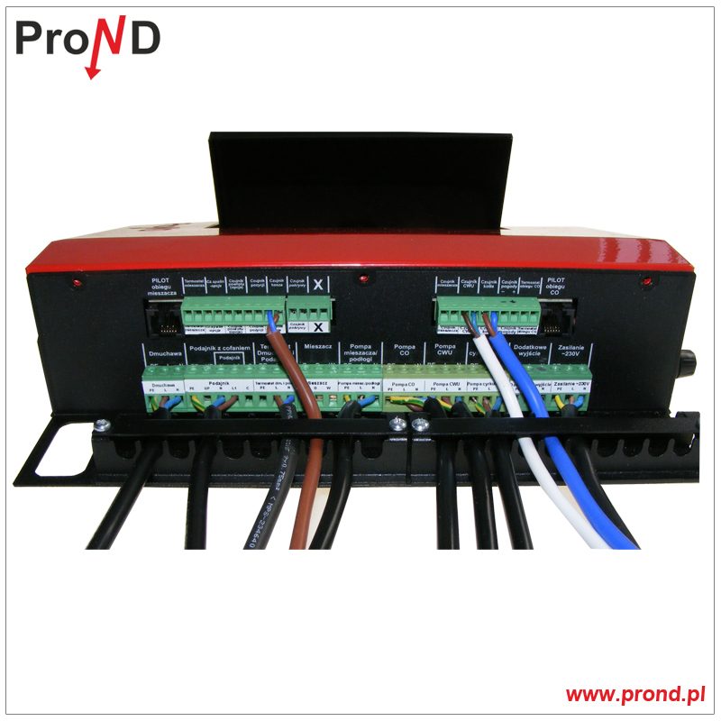
1R - wersja do montażu na kotle lub zasobniku z opałem, wyprowadzenie przewodów w tylnej części sterownika. Logotyp z prawej strony może zostać zastąpiony logotypem producenta urządzenia grzewczego.

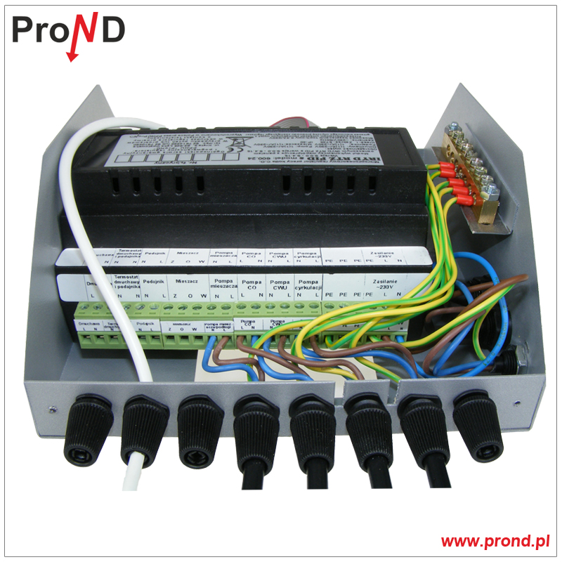
Moduł + panel - Moduł wykonawczy i panel osobno (bez obudowy metalowej)
Specjalny panel operatorski z zatrzaskami umożliwia jego montaż na elewacji kotła. Moduł wykonawczy posiada specjalne zatrzaski za pomocą których mocuje się go na szynie DIN 35 mm. W pełni rozłączalna konstrukcja umożliwia łatwy montaż i ewentualny serwis, przewody przyłączeniowe poszczególne urządzenia wykonawcze oraz czujniki pozostają integralną częścią pieca bądź pomieszczenia kotłowni i mogą być zabudowane w kotle lub w ścianach budynku.

Wersja NK - nakotłowa - wersja do zabudowy na bocznej ścianie kotła, w miejscu niewidocznym dla operatora. W tej wersji zastosowano wysokiej jakości złącza przemysłowe do podłączenia czujników. Panel operatorski montowany w przedniej ścianie izolacji kotła lub na kotle w ruchomym pulpicie. Dwie części obudowy połączone ze sobą taśmą wielożyłową.

SW2 - wersja do obsługi dużych kotłów. Montaż na zabudowie kotła, obsługa urządzeń 3 fazowych. Zastosowanie obudowy z szyną DIN pozwala na montaż dodatkowych styczników np. do trójfazowych pomp


Wersje wzmocnione
- wersja wzmocniona: dmuchawa 550W podajnik 250W pompy 250W dostępna w obudowach 1S, 1S pełnej, 0S
- wersja wzmocniona: dmuchawa, podajnik pod stycznik: pod wyjście podajnik można podłączyć cewkę stycznika, dmuchawa wzmocniona 550W pompy 250W, dostępna w obudowach 1S, 1S pełnej, 0
UKŁAD PRACY REGULATORA
1) Układ z pompą CO i pompą CWU
W tej instalacji pompa CO zasila instalację związaną z ogrzewaniem pomieszczeń. Pompa ładująca zasobnik CWU nagrzewa wodę wykorzystywaną w instalacji CWU.

2) Układ z pompą CO zasilającą grzejniki, pompą mieszacza z mieszaczem sterowanym siłownikiem w obiegu podłogówki, pompą ładującą zasobnik CWU, pompą cyrkulacyjną w obiegu cyrkulacji CWU
W tym układzie pompa CO zasila instalację związaną z ogrzewaniem pomieszczeń z zainstalowanymi grzejnikami. Instalacja podłogówki zasilana jest poprzez oddzielnie regulowany obieg składający się z pompy mieszacza oraz siłownika zaworu mieszającego. Zawór mieszający może być trójdrogowy lub czterodrogowy. Pompa ładująca zasobnik CWU nagrzewa wodę wykorzystywaną w instalacji CWU. Pompa cyrkulacyjna pracuje w obiegu cyrkulacji CWU zapewniając ciepłą wodę w kranach od razu po ich odkręceniu.

3) Instalacja z pompą CO, obiegiem instalacji grzejnikowej z siłownikiem zaworu mieszającego, pompą ładującą zasobnik CWU, pompą cyrkulacyjną CWU.
W tym układzie pompa CO zasila instalację związaną z ogrzewaniem pomieszczeń z zainstalowanymi grzejnikami w pierwszym obiegu. Drugi obieg grzejnikowy zasilany jest poprzez oddzielnie regulowany obieg składający się z pompy mieszacza oraz siłownika zaworu mieszającego. Zawór mieszający może być trójdrogowy lub czterodrogowy. Pompa ładująca zasobnik CWU nagrzewa wodę wykorzystywaną w instalacji CWU. Pompa cyrkulacyjna pracuje w obiegu cyrkulacji CWU zapewniając ciepłą wodę w kranach od razu po ich odkręceniu.

4) Instalacja z pompą CO, obiegiem instalacji podłogowej z zaworem mieszającym ręcznym lub termostatycznym, pompą ładującą zasobnik CWU, pompą cyrkulacyjną CWU.
W tym układzie pompa CO zasila obieg grzejnikowy. Instalacja podłogówki zasilana jest poprzez oddzielnie regulowany obieg składający się z pompy mieszacza oraz zaworu mieszającego ręcznego lub termostatycznego (trójdrogowego lub czterodrogowego). Czujnik można zamontować na powrocie z podłogówki. Jeśli temperatura powrotu osiągnie wartość żądaną, pompa podłogi zostaje wyłączona. Pompa ładująca zasobnik CWU nagrzewa wodę wykorzystywaną w instalacji CWU. Pompa cyrkulacyjna pracuje w obiegu cyrkulacji CWU zapewniając ciepłą wodę w kranach od razu po ich odkręceniu.

5) Instalacja z pompą CO, obiegiem instalacji podłogowej z siłownikiem zaworu mieszającego, pompą ładującą zasobnik CWU, pompą cyrkulacyjną zasilającą dodatkowy obieg grzejnikowy
W tym układzie pompa CO zasila instalację związaną z ogrzewaniem grzejnikowym 1. Pompa cyrkulacyjna zasila dodatkowy obieg grzejnikowy 2, dla tej pompy można ustawić przerywaną pracę oraz godziny, w których ma pracować. Instalacja podłogówki zasilana jest poprzez oddzielnie regulowany obieg składający się z pompy mieszacza oraz siłownika zaworu mieszającego. Zawór mieszający może być trójdrogowy lub czterodrogowy. Pompa ładująca zasobnik CWU nagrzewa wodę wykorzystywaną w instalacji CWU.

6) Instalacja z pompą CO, obiegiem instalacji podłogowej z siłownikiem zaworu mieszającego, pompą ładującą zasobnik CWU, pompą cyrkulacyjną zasilającą wymiennik płytowy
W tym układzie pompa CO zasila instalację związaną z ogrzewaniem grzejnikowym. Instalacja podłogówki zasilana jest poprzez oddzielnie regulowany obieg składający się z pompy mieszacza oraz siłownika zaworu mieszającego. Zawór mieszający może być trójdrogowy lub czterodrogowy. Pompa ładująca zasobnik CWU nagrzewa wodę wykorzystywaną w instalacji CWU. Obieg grzejnikowy i podłogowy zasilany jest przez wymiennik płytowy. Do zasilenia wymiennika wykorzystana została pompa cyrkulacyjna.

7) Instalacja z pompą CO zasilającą grzejniki, pompą mieszacza z mieszaczem sterowanym siłownikiem w obiegu podłogówki, pompą ładującą zasobnik CWU, pompą cyrkulacyjną w obiegu cyrkulacji CWU, pompą kotłową.
W tym układzie pompa CO zasila instalację związaną z ogrzewaniem pomieszczeń z zainstalowanymi grzejnikami. Instalacja podłogówki zasilana jest poprzez oddzielnie regulowany obieg składający się z pompy mieszacza oraz siłownika zaworu mieszającego. Zawór mieszający może być trójdrogowy lub czterodrogowy. Pompa ładująca zasobnik CWU nagrzewa wodę wykorzystywaną w instalacji CWU. Pompa cyrkulacyjna pracuje w obiegu cyrkulacji CWU zapewniając ciepłą wodę w kranach od razu po ich odkręceniu. Dodatkowo stosowana jest tutaj pompa kotłowa która pomaga dogrzewać powrót kotła.

8) Instalacja z pompą mieszacza i mieszaczem sterowanym siłownikiem w obiegu grzejnikowym, pompą ładującą zasobnik CWU, pompą cyrkulacyjną w obiegu cyrkulacji CWU, pompą mieszacza wspomagającą.
W tym układzie zastosowano dodatkową pompę wspomagającą krążenie czynnika w krótkim obiegu kotła. W przypadku jeśli przekrój rur jest niewystarczający, w układzie jest dużo kolan, przewężeń stosowanie takiej pompy jest konieczne aby podczas zamknięcia siłownika zaworu czynnik krążył z zasilania na powrót kotła. Zasilanie pompy wspomagającej w tym przypadku należy połączyć równolegle z zasilaniem pompy mieszacza (pod jedno wyjście „pompa mieszacza” podłączamy dwie pompy).

9) Instalacja z pompą mieszacza i mieszaczem sterowanym siłownikiem w obiegu grzejnikowym, pompą ładującą zasobnik CWU, pompą cyrkulacyjną w obiegu cyrkulacji CWU, bez pompy mieszacza wspomagającej.
Na rysunku poniżej przedstawiono taki sam układ jak w punkcie 8 tylko bez pompy mieszacza wspomagającej. W tej sytuacji przekrój i ułożenie rur w krótkim obiegu kotła (grube rury na rysunku) muszą być odpowiednio dobrane przez hydraulika, tak aby zapewnić krążenie grawitacyjne gdy siłownik mieszacza zamknie zawór całkowicie. Jeśli warunki nie będą spełnione może dojść do sytuacji gdzie po zamknięciu zaworu temperatura powrotu kotła nie będzie wzrastała. W takim przypadku należy stosować pompę wymuszająca obieg jak w punkcie 8.
